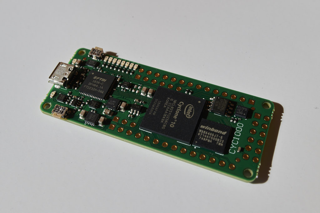
CYC1000 is a tiny, 62.5 by 25mm FPGA board that has exactly the bare minimum of what is required for PDP2011. It has the latest generation Cyclone-10 FPGA and DRAM memory, a few leds and just enough free GPIO pins. The FPGA is big enough – with room to spare – to run PDP2011 configured as an 11/70 with FPP, disk controller, serial ports, and DELUA ethernet controller. The board uses a FTDI chip for FPGA programming, and that can also be used for the console of the PDP2011. A second serial port is possible too.
You’ll very likely want to connect an SD card, and the easiest way to do that is to use PMODs – usually those can be bought from the same place that you’ll find CYC1000 in. If you want to use Ethernet – for instance for 2.11BSD or RSX-11M you can also add a PMODNIC100.
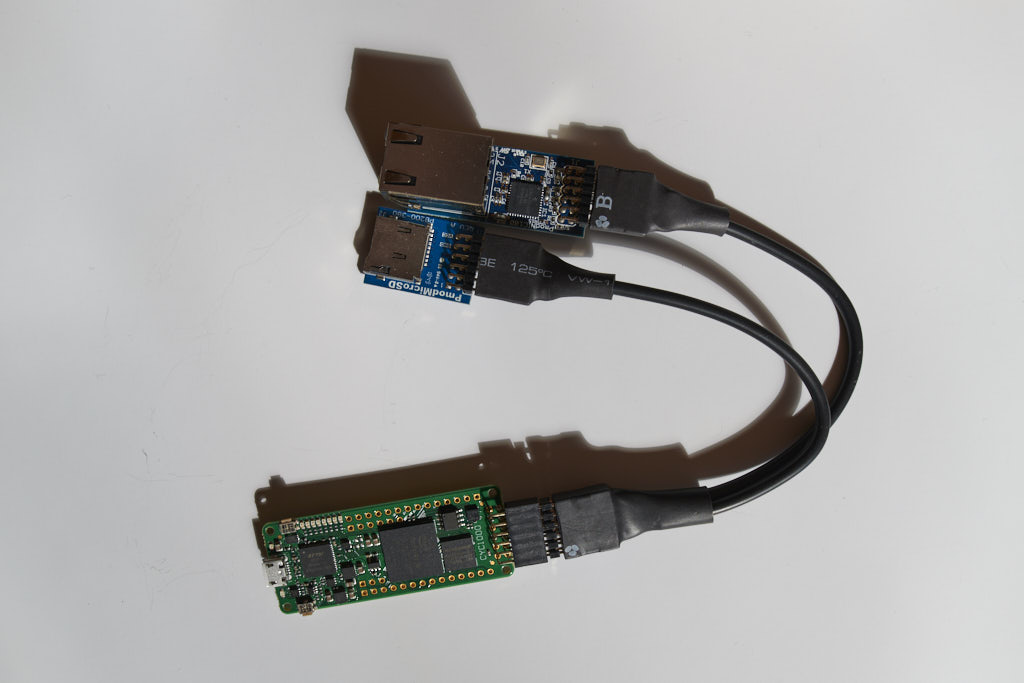
This shows the CYC1000 with a 2×6 angle female header soldered on, and an old Digilent 2×6 to dual 6-pin splitter cable – they used to give those away with the 12-pin PMODs, but now they’re sold as an accessory. The easiest way by far to connect the PMODs.
I should point out here that you’ll need to make sure the power pins on the PMODs don’t touch anything – the power lines are not fused, so a short might very well destroy your board!
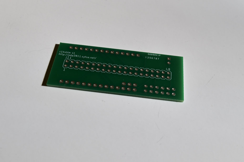
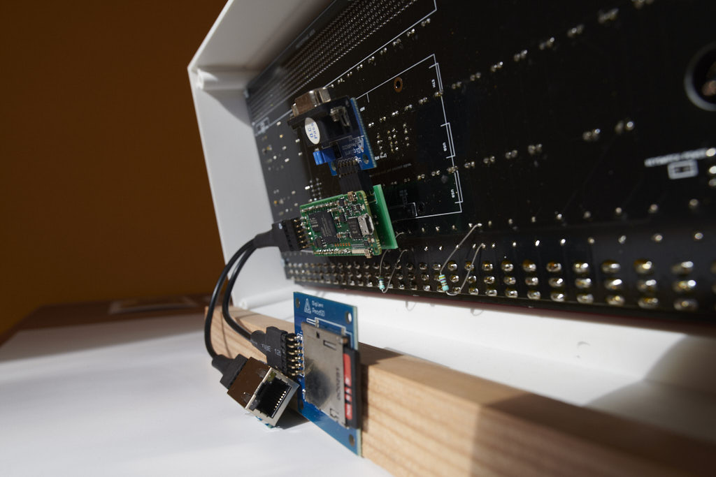
To hook up the CYC1000 to Oscar Vermeulen’s PiDP-11 console, I’ve designed a shim – it is soldered onto the back of the CYC1000 and plugs into the 2×20 connector on the console. When soldering the two boards together, pay attention – there is an order in which you’ll have to do the soldering!
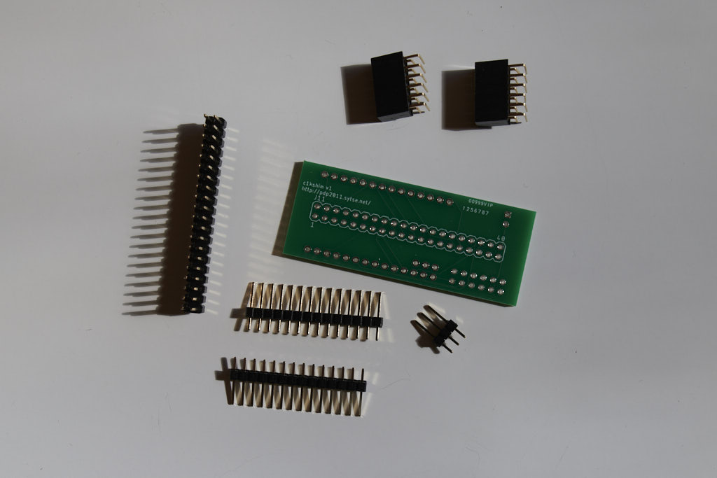
This is what you’ll need to connect the shim.
The 2×20 should be soldered in first, then the 2×6 angled header. You can omit this if you’re sure you will never use the 2nd serial port (and you’ll always use the FTDI chip for the console). And if you didn’t already, the other 2×6, the one for the SD card and the PMODNIC100, should at this point be soldered onto the CYC1000, before joining the the two boards.
Then the boards are joined by both 1×14 and 1×3 headers. Easy as that – although I’ve found that the CYC1000 board doesn’t seem to ‘take’ the solder easily. Check for cold welds!
I made the first prototype with the 2×6 angle header for the serial port wedged in between the CYC1000 and the shim – and using that as a reference for the distance between the two boards. For the later boards, I mounted the 2×6 angle header under the shim, so that the two boards are only kept apart by the plastic bits on the 1×14 and 1×3 headers. It’s more compact that way and looks a bit nicer – except for the header pins sticking out a bit, but that’s hidden away underneath.
The CYC1000 plus shim weighs next to nothing, so I didn’t see the point to add any mechanical connections. I omitted screw holes in the shim board (ehh, I should probably admit to that I didn’t know how to make those, and was too lazy to measure exactly where they should go too).
Soldering the two boards together may sound a bit permanent. It is. But it leaves a lot of room in the PiDP console box, and if you use sockets it might not all fit.
The CYC1000 used to have a major disadvantage: the documentation was not very useful. There’s a recent (02/2020) version that is a lot better though. Try this link here or look for a document called ‘User Guide’ on their website in case the link fails.
About the ‘bypass’ resistors: In Oscar’s schematic for the PiDP-11 console, there are three resistors named ‘R_ROW1’, ‘R_ROW2’ and ‘R_ROW3’. Depending on the version of the kit, these are 1kOhm or 820Ohm. Both will work fine with the Raspberry Pi, but the FPGA will most likely not work with the 1kOhm – and also maybe not with the 820Ohm version. This is due to the difference in the internal pullup resistors in the RPi and the FPGAs – and also differences between production runs.
There’s an easy way to check if your console needs the ‘bypass’ resistors – put the processor in halt, set the lower selector to Bus Reg, then start flipping the numbered switches starting from 0 going towards 11. The corresponding Data LEDs should come on one by one – and if you reach 11 that way, you’re fine. But if instead all previous LEDs turn off if you flip the next switch, then the ROW resistor value is too high.
Ideally of course you would replace the resistor. But because it’s on the front of the PCB, it’s just a lot easier to add another resistor in parallel (hence ‘bypass’). Probably any value under 800 or so Ohm will work – or even a bit of wire. I happened to have a bunch of 5Ohm resistors near, so I used those.