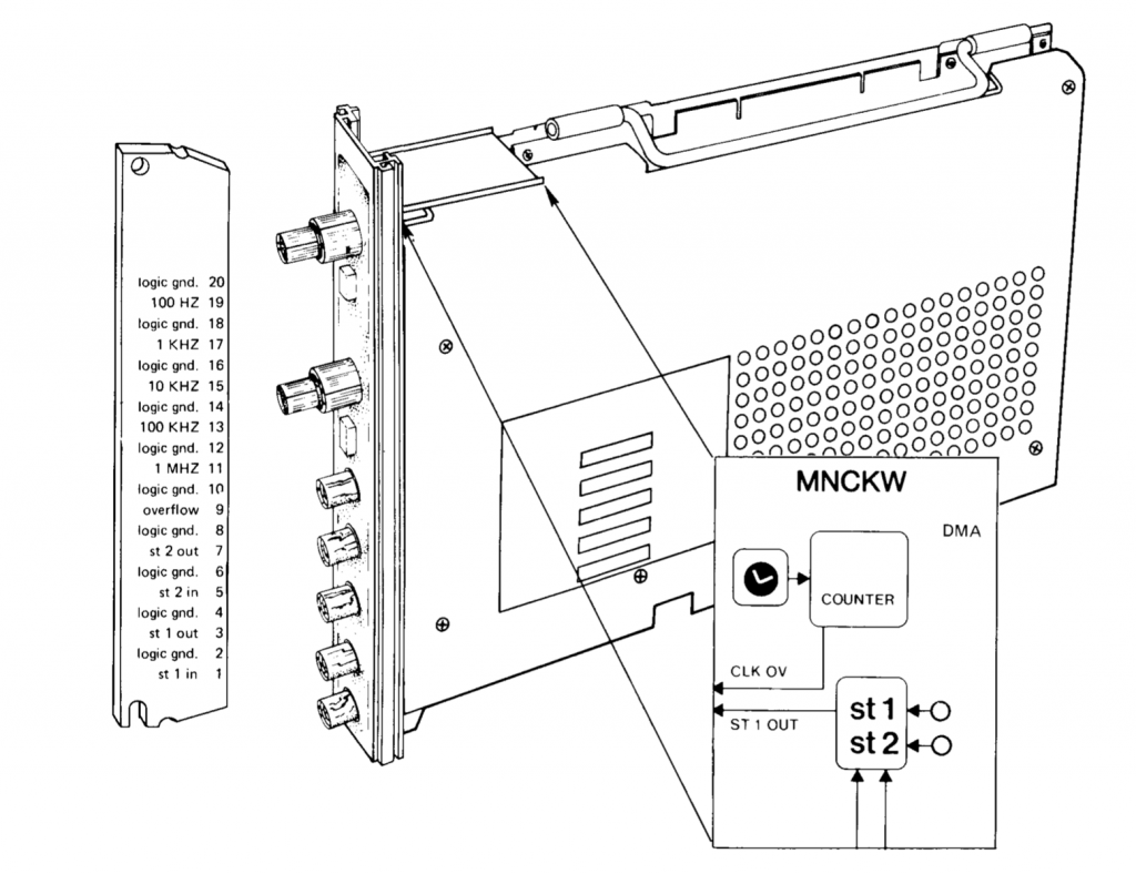
MNCKW is a precision clock. It can trigger timed events, or keep track of the timing of external or internal events. Also, it has two special Schmitt trigger inputs that can be used to start the clock, or linked to the MNCAD to start a conversion, or to link to the clock and count impulses. The level that the Schmitt triggers will fire on is set by pot meters on the front panel. The front panel also has the two Schmitt trigger inputs and outputs, and a special counter overflow output.
Because MNCKW can be used both for timing events and for triggering, it is useful to have two modules in a system – so that the event timing can be run independently of the triggering. In that case, the first MNCKW will be linked to the MNCAD; the second will be unconnected – meaning its Schmitt triggers and overflow will not set off events in other modules.
MNCKW0  CSR 171020  VEC 440/444  BR 4
MNCKW1  CSR 171024  VEC 450/454  BR 4
MNCKW uses two addresses on the bus; one for the CSR and one for the counter/preset registers – it depends on the state of the MNCKW if the second address will act as the counter or as the preset register.
MNCKW CSR
| 15 | st2flag (R/W) Set to 1 by the MNCKW if ST2 has fired. |
| 14 | stintenable (R/W) When set to 1 and either the st1flag or the st2flag is set – by firing the corresponding Schmitt trigger – then cause an interrupt to the second vector. |
| 13 | st2goenable (R/W) When this bit is set to 1 and ST2 fires, the go bit will be set – thereby starting the clock. At the same time the st2goenable bit itself will be reset. |
| 12 | for (R/W) ‘flag overflow?’ This bit is set to 1 by the MNCKW if either one of the Schmitt triggers fires or a counter overflow occurs, and the corresponding flag in the CSR was already set. |
| 11 | disintosc (R/W) Disconnect the internal oscillator from the 10Mhz frontend, effectively stopping the clock. This is used for MAINDEC testing of the module, in combination with the maint-st1 flag. |
| 10 | st1flag (R/W) Set to 1 by the MNCKW if ST1 has fired. |
| 9 | maint-st2 (W/O) Writing a 1 into this bit will simulate a trigger on ST2. Reading this bit will always return 0. |
| 8 | maint-st1 (W/O) Writing a 1 into this bit will simulate a trigger on ST1. If the disintosc bit is set, this will also cause the (disconnected) 10Mhz frontend to receive a pulse; so that on every 10th count the 1Mhz stage will receive a pulse, and so on. Reading this bit will always return 0. |
| 7 | ovfflag (R/W) Set to 1 by MNCKW on overflow of the clock counter. |
| 6 | ovfintenable (R/W) If set to 1 and ovfflag becomes set, then MNCKW will cause an interrupt to the first vector. |
| 5:3 | rate (R/W) The rate of the clock counter is set from these three bits as follows: 000 : the clock is stopped 001 : 1Mhz 010 : 100kHz 011 : 10kHz 100 : 1kHz 101 : 100Hz 110 : the clock will count ST1 impulses 111 : the clock will use line frequency (50/60Hz) |
| 2:1 | mode (R/W) The clock mode, as follows: 00 : MODE1 Single interval: count once from the preset value up to zero, set the overflow flag, and stop. 01 : MODE2 Repeat interval: count from the preset value up to zero; set the overflow flag; reload the preset value into the counter. 02 : MODE3 The counter is free running. A pulse on ST2 will copy the counter value to the buffer/preset register, and set the overflow flag. 03 : MODE4 Same as MODE3, but on receiving ST2 the counter will be set to zero. |
| 0 | go (R/W) enables the counter to run when set to 1. |
MNCKW BUF
The second address of the MNCKW is backed by two registers – the counter and the buffer/preset. When the clock is stopped, a value written to this address will update both the counter and the preset value. When the clock is running, only the preset value is updated. Reading from this address will get the preset value, or in mode 2 and 3 the last copied counter value.
Information sources
The information about MNCKW is derived from
- the listing of the X11 module XMNCA0 on Bitsavers http://bitsavers.org/pdf/dec/pdp11/xxdp/x11_listings/AC-F422A-MC_CXMNCA0-MNCKW_Feb79.pdf
- The LPS documentation from the University of Queensland, also hosted on Bitsavers http://bitsavers.org/www.computer.museum.uq.edu.au/pdf/DEC-11-HLPGA-C-D%20LPS11%20Laboratory%20Peripheral%20System%20User’s%20Guide.pdf and http://bitsavers.org/www.computer.museum.uq.edu.au/pdf/DEC-11-HLPMA-B-D%20LPS11-S%20Laboratory%20Peripheral%20System%20Maintenance%20Manual.pdf
- the schematics of the module; the best quality scan I found is in this file http://bitsavers.org/pdf/dec/pdp11/minc/MP00652_MNC11_Schematics_Jul78.pdf
Unknown/Missing information
The main issue at the moment is that the VMNC test expects the counter to reset to 0, when in rate 0 and an ST1 pulse is received. It sort-of makes sense, but I can’t find evidence of a circuit that causes this in the schematic.
Implementation status
No issues known; all MINC BASIC functions appear to work as they should.