In the first volume of the MINC book set ‘Introduction to MINC’ several demonstration programs are mentioned. These demonstration programs (and a few more) are on the demo diskette image that you can find on Bitsavers. And if you follow the process I described in the previous post, the demo programs will end up on the RK image.
So, playtime. I selected the DADEM to give a try – a demonstration of the DA module.
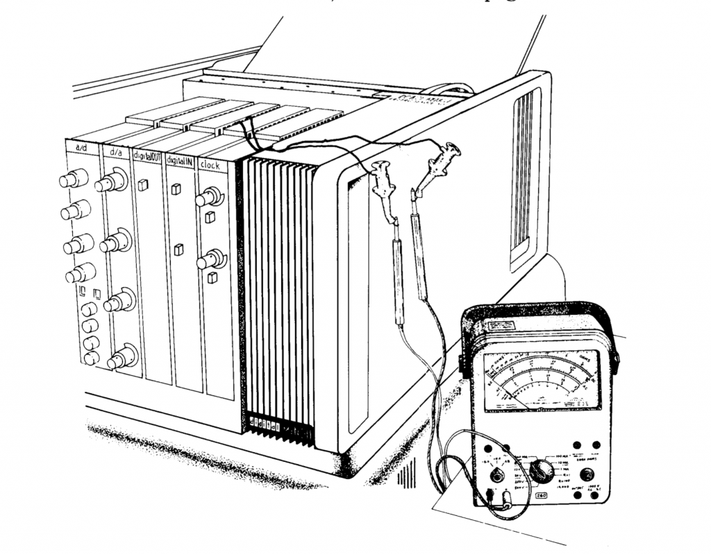
For the D/A part, I had already added a driver for the PMODDA2 – I had one of those lying around. Not ideal maybe, since it only has two channels, and it’s limited to 0V-3.3V – the original MNCAA could be set to 5 different voltage ranges with knobs on the front panel, up to -10.24V to +10.235V!
Anyway, of course in my first experiments I hooked up my trusty digital voltmeter and everything worked great – but digital voltmeters do lack the proper mad scientist feeling that real meters with swinging needles give. So I just had to go into my storage room and dig out the box with old toys to find something more fitting.
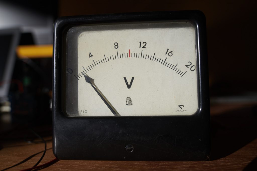
And there it is. I’m not quite sure how old it is, but definitely older than I am – my dad took it home with him for his kids to play with, in the early 70s. It came from a laboratory instrument that his employer had discarded – probably a heavy power supply with lots of valves in it. For years the meter figured next to the transformer in various Fischer-Technik setups, later on I used it for my dangerous electrolysis prototypes… and it’s brother, taken from another instrument became the show piece on the front panel of my home made audio amplifier that I used in various offices until late in 1999. The amplifier is no more, but I still have the meter.
Anyway, the demo. It makes the voltmeter swing around for a settable number of seconds, and it’s remarkably unimpressive – given that the range of 0V-3.3V is not really doing a lot on a 0-20V scale. I’ll have to look into level converters next. It’s not that bad with MNCAA really, but the ‘wrong’ input range conversion with MNCDA is a bit jarring – that needs fixed.
For convenience, here’s the listing of the test program. If you are going to give it a go, take line 22 out – it will likely mess up the terminal emulator. Yes, it would be great if the terminal emulator in PDP2011 would be vt105 compatible… hmm, I’ll think about it.
10 REM -----DADEM
20 REM ----------Program to put analog out to digital volt ohmmeter
22 DISPLAY_CLEAR
30 PRINT 'DIGITAL-TO-ANALOG DEMONSTRATION PROGRAM' \ PRINT
40 PRINT 'The digital-to-analog demonstration program  generates a voltage'
50 PRINT 'at the D/A output causing the volt-ohmmeter to oscillate starting'
60 PRINT 'with a small amplitude and slowly increasing until a maximum'
70 PRINT 'amplitude is reached.'
80 PRINT
90 PRINT 'Connect the volt-ohmmeter to one of the four channels of the D/A'
100 PRINT 'converter.  Set the volt-ohmmeter to DC volts and select a range'
110 PRINT 'that will give  full-scale deflection for a 5 volt input.'
120 PRINT
130 REM Request user input
140 REM
150 PRINT 'How many seconds do you wish to run (1 to 30)'; \ INPUT T
151 PRINT 'How many D/A converters do you have in your configuration';
152 INPUT N
153 IF N>=1 THEN IF N<=4 THEN  GO TO 157
156 PRINT 'please specify an integer between 1 and 4' \ GO TO 151
157 IF N>1 GO TO 600
160 PRINT USING 'What channel did you connect the volt-ohmmeter to (0 to ##)',4*N-1; \ INPUT C
170 L=127 \ M=.5 \ A=16 \ D=1 \ V=0
180 REM Schedule an interrupt T seconds from now
200 S=0
210 SCHEDULE('Interval',T,420)
270 REM Repeat the following code until interval complete
290 IF S=1 THEN 500
300 AOUT(,V,,,C)
310 GOSUB 330
320 GO TO 290
330 V=V+A*D
334 IF D*V<ABS(L) THEN 400
336 D=-D
340 L=-L
350 IF L<0 THEN 400
360 IF L<200 THEN 380
370 IF L<2000 THEN 390
380 M=1/M
390 L=L*M
400 RETURN
410 GO TO 150
420 REM Set the done flag.
430 S=1
440 RETURN
500 PRINT  \ PRINT 'AGAIN (Y or N)'; \ INPUT A$
510 IF A$='Y' THEN 120 \ IF A$='y' THEN 120
520 IF A$='N' THEN 800 \ IF A$='n' THEN 800
530 PRINT 'Please answer Y or N' \ GO TO 500
600 PRINT 'If you have followed the suggested configuration rules then your modules'
601 PRINT 'are addressed as follows:' \ PRINT
602 PRINT 'The rightmost d/a converter in the chassis has lines    0-3'
610 PRINT 'The next d/a converter to the left has lines:           4-7'
620 IF N=2 THEN 700
630 PRINT 'The next d/a converter to the left has lines:           8-11'
640 IF N=3 THEN 700
650 PRINT 'The next d/a converter to the left has lines:           12-15'
700 GO TO 160
800 END
Another thing with this test program – and the other one that I played around with, the DODEM for digital output – is that they use statements like SCHEDULE and PAUSE. Those require that the SJ monitor is sysgenned with timer support – if you didn’t, then those statements won’t work. And another thing: the sysgen needs to match the actual rate of the KW11 line clock in your system. Yes, I managed to get that wrong too 😉