My last post was about playing with the GPIB support in MINC and my Philips PM6666. A very capable and unassuming counter – it doesn’t take up a lot of space, it makes no noise, it doesn’t get hot or consume lots of power. I don’t worry about leaving it on when I’m not there – well, the power entry module RIFA already blew up, but that’s been replaced.
There’s only one thing wrong with the PM6666 really – it’s LCD display is a bit hard to read in my dim workshop. So when I ran into a ‘reasonably priced’ HP 5335A, I couldn’t resist – not even when the listing said that it didn’t work without specifying exactly what didn’t. I thought it’d probably be something simple, and a nice challenge to figure out a solution for.
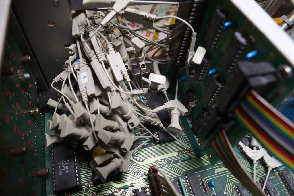
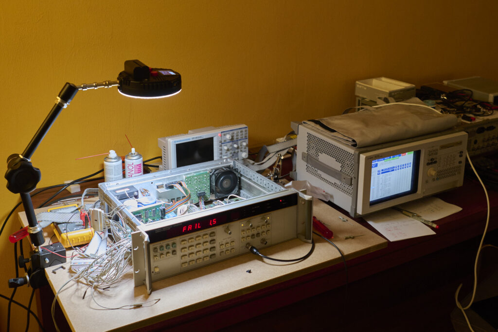
That took me a while, I should say – mostly because the little voice in the back of my head kept saying ‘sure, you’ve established beyond all reasonable doubt that the ROM is broken, but what else might be wrong with it’. But all that was quickly resolved when I happened to find another ‘reasonably priced’ HP 5335A. And just another couple late night ebay orders later, I’ve not just fixed the problems of the first one, I now suddenly have two working units!
So next to the PM6666 – small, unassuming, unobtrusive, now I have two HP 5335A – very large, very loud, consuming an inordinate amount of energy and producing worrying amounts of heat – but also with lots and lots of very nice red seven segment displays. And also very, very precise, and very much early-eighties in their GPIB implementation.
In comparison with the PM6666 or later instruments, no, a 5335A doesn’t do ID commands. A 5335A can report its current setup, but partially – notably, the gate time is missing. And where the PM6666 reports the setup in sort-of readable text, the 5335A reports it in binary.
10 I%=15
20 SEND("PQ ",I%)
30 RECEIVE(A$,,I%)
40 IF LEN(A$)<2 THEN 30
50 IF LEN(A$)>=30 THEN 70
60 PRINT "error" \ STOP
70 PRINT "FN=";ASC(SEG$(A$,1,1))
80 PRINT "B2=";ASC(SEG$(A$,2,2))
90 PRINT "GC=";ASC(SEG$(A$,3,3))
100 PRINT "CA=";ASC(SEG$(A$,4,4))
110 PRINT "CB=";ASC(SEG$(A$,5,5))
120 PRINT "AR=";ASC(SEG$(A$,6,6))
130 FOR I=7 TO 14 \ PRINT USING " ###",ASC(SEG$(A$,I,I)); \ NEXT I
140 PRINT
150 FOR I=15 TO 22 \ PRINT USING " ###",ASC(SEG$(A$,I,I)); \ NEXT I
160 PRINT
170 FOR I=23 TO 30 \ PRINT USING " ###",ASC(SEG$(A$,I,I)); \ NEXT I
180 PRINT
and that might produce output like
T5H35P    13-AUG-86  23:35:43

FN= 1
B2= 0
GC= 0
CA= 32
CB= 0
AR= 0
   0   0   0   0   0   0   0   0
   0  16   0   0   0   0   0   0
   0  16   0   0   0   0   0   0

READY
Ok no that isn’t very informative – but that’s the point: MINC Basic isn’t very well suited to decode bit fields, it’s too much work to properly decode what is in those strings, and later instruments are just easier to work with. Sure, you could copy the setup and push it back, but it’d be so much more useful if it was in a readable format.
With that off my chest, let’s try a basic measurement. I’ve set up the generator for a 1MHz sine wave and connected that to the A input, and set the 5335A for the most basic config – initialize, and function 1 – FREQ A in R2D2 speak. The first thing that stands out is that the 5335A doesn’t recognize the end of the MINC strings like all my other instruments do – note the extra trailing space in line 20 below. If you omit that, it’ll just wait until it finds a separator in some future command.
10 I%=15
20 SEND("in fn1 ",I%)
30 RECEIVE(A$,,I%)
40 PRINT CLK$;" ";LEN(A$);A$
50 GO TO 30
but then note the output:
T5H35C    13-AUG-86  23:53:24

23:53:25  19 F    +999.99964E+03
23:53:27  19 F    +999.99964E+03
23:53:27  0
23:53:28  19 F    +999.99964E+03
23:53:29  19 F    +999.99964E+03
23:53:29  0
23:53:31  19 F    +999.99963E+03
23:53:32  19 F    +999.99964E+03
What’s with all those zero length strings? I’m not sure, but I’m getting those on both the 1.0 and 1.1 firmware versions. Maybe the issue that was described in the 1.1 update document was related and timing dependent?
Does it work with the serial poll? Sure:
10 I%=15
20 SRQ_SUBROUTINE(90)
30 SEND("in wa1 sr1 ",I%)
40 TRIGGER_INSTR(I%)
50 FOR I=1 TO 5
60 PAUSE(.2)
70 NEXT I
80 GO TO 40
90 REM this is the serial poll subroutine
100 SERIAL_POLL(D%,,I%)
110 RECEIVE(A$,,I%)
120 IF LEN(A$)<2 THEN 110
130 PRINT CLK$;" ";A$
140 RETURN
but note line 120 – and yes, that seems necessary for both the 1.0 and 1.1 versions of the firmware.
T5H35D    14-AUG-86  00:27:28

00:27:29 F    +999.99961E+03
00:27:30 F    +999.99961E+03
00:27:32 F    +999.99961E+03
00:27:33 F    +999.99961E+03
00:27:34 F    +999.99961E+03
00:27:36 F    +999.99961E+03
00:27:37 F    +999.99962E+03
Anyway, instead of replicating the entire previous post with the 5335A – how about if I try to have both units measure at the same time, how would that work? Obviously it’d have to use serial poll and reading the results asynchronously.
The way MINC Basic deals with the SRQ signal, as I’ve described in the previous post, is through the SRQ_SUBROUTINE and SERIAL_POLL commands. Yes, you can list more than one GPIB address to poll on the SERIAL_POLL command – but it still just polls the listed instruments serially, so it’s mostly a notational convenience over using two separate commands. For one, you’d still have to figure out in software which of the units raised the SRQ signal. And because it reports the responding instrument by index – not by address… another of those ideas that were probably bright at the time, but not that useful if you actually try to wotk with them. I find it easier to just poll each instrument directly. Like so:
10 I%=15
20 J%=16
30 SRQ_SUBROUTINE(110)
40 SEND("in wa1 sr1 ",I%)
50 SEND("in wa1 sr1 ",J%)
60 TRIGGER_INSTR(I%,J%)
70 FOR I=1 TO 25
80 PAUSE(.1)
90 NEXT I
100 GO TO 60
110 REM this is the serial poll subroutine
120 K%=I%
130 SERIAL_POLL(D%,C,I%)
140 IF C=1 THEN 190
150 K%=J%
160 SERIAL_POLL(D%,C,J%)
170 IF D%<>65 THEN RETURN
180 IF C=1 THEN 190
190 RECEIVE(A$,,K%)
200 IF LEN(A$)<2 THEN 190
210 PRINT CLK$;" ";D%;" ";K%;" ";A$
220 RETURN
and that produces something like this:
T5H35E    14-AUG-86  00:44:31

00:44:31  65   16  F     +999.9999E+03
00:44:32  65   15  F    +999.99964E+03
00:44:34  65   16  F    +1.0000000E+06
00:44:34  65   15  F    +999.99964E+03
00:44:36  65   16  F    +1.0000000E+06
00:44:36  65   15  F    +999.99964E+03
00:44:38  65   16  F     +999.9999E+03
00:44:39  65   15  F    +999.99963E+03
00:44:40  65   16  F     +999.9999E+03
00:44:41  65   15  F    +999.99964E+03
00:44:43  65   16  F    +1.0000000E+06
00:44:43  65   15  F    +999.99964E+03
00:44:45  65   16  F    +1.0000000E+06
00:44:46  65   15  F    +999.99964E+03
00:44:47  65   16  F    +1.0000000E+06
00:44:48  65   15  F    +999.99964E+03
00:44:50  65   16  F     +999.9999E+03
00:44:50  65   15  F    +999.99963E+03
00:44:52  65   16  F    +1.0000000E+06
except when I shorten the gate time on the V1.1 firmware unit – the one with address 15, it starts producing spurious measurements. Not sure what is going on there, I’ll need to do some more research. But I already kind of know the answer: this is GPIB like it’s 1980.
(edit, added Aug 23, ten days later) Yes, that bit of BASIC is a disgrace, and just asking for 1980-like problems. Here’s a better version:
10 I%=15
20 J%=16
30 SRQ_SUBROUTINE(110)
40 SEND("in wa1 sr1 ",I%)
50 SEND("in wa1 sr1 ",J%)
60 TRIGGER_INSTR(I%,J%)
70 FOR I=1 TO 20
80 PAUSE(.1)
90 NEXT I
100 GO TO 60
110 REM this is the serial poll subroutine
120 K%=I%
130 GOSUB 170
140 K%=J%
150 GOSUB 170
160 RETURN
170 REM handle serial poll for instrument k%
180 SERIAL_POLL(D%,C,K%)
190 IF C=0 THEN RETURN
200 IF D%<>65 THEN RETURN
210 RECEIVE(A$,,K%)
220 IF LEN(A$)<2 THEN 210
230 PRINT CLK$;" ";D%;" ";K%;" ";A$
240 RETURN
but that doesn’t fix the issue: the V1.1 unit still sends spurious measurements while the V1.0 unit doesn’t. But completely unrelated, I did actually see the V1.1 unit produce the duplicate character that the update documentation warns about. So yes, that is real.