MINC means Modular Instrument Computer.
Before MINC, DEC had other lab hardware – most obviously LPS-11, but also components that could be put together to make up something similar – A/D modules, digital input/output modules, precision clocks. But MINC was probably the first real integrated system – and maybe also the first real attempt at a closed system. The documentation that I’ve found so far completely lacks a programmer’s view on the MINC modules – and also I’ve not found any reference that such documents were ever published. Still, there was also something called a ‘Foundation Module’ – so maybe it is just the passing of time which has made the proper documentation disappear.
Basically, the MINC was a ‘special’ PDP-11 – 11/03 or 11/23, with RX or RL drives and a backplane into which the owner could install the special MINC modules. Quite flexible, although there were certainly limits imposed by the software that DEC supplied to control the setup. And yes, only 8 slots – I have 6 in my ‘simple’ test setup already.
So which modules were there? First of all and probably the most complex of all MNCAD, the A/D converter – most complex because it could be extended with several MNCAM analog multiplexers and MNCAG analog preamplifiers – to the point that a single A/D setup would possibly exhaust all the space in the MINC backplane. The hardware and software allows for up to 64 analog channels, but with a maximum of 8 slots to put modules in, I’m not sure that realistic configurations would reach that.
You’d be able to use it quite easily though – just sample the values into a simple basic program. Like so:
5  DIM V(8)
10 AIN(,V(),8,1,0,8)
20 FOR I=0 to 7
30 PRINT V(I);
40 NEXT I
50 PRINT
60 GO TO 10
which would give you a line of samples of 8 analog input lines every second. Something like this:
1.05249 2.00732 -5.11987 -5.11987 1.05249 2.00732 -5.11987 -5.11987
from my current test setup – I’ve linked inputs 0+4, 1+5 to resistors to set the value to ~1V and ~2V, and the others are connected to ground – and the software assumes the standard range of -5.12 to +5.12V.
The next likely module to encounter is probably MNCKW – the dedicated clock. The base system of the MINC would already have the usual KW11L line frequency clock, but the MNCKW can do a lot more – it has external triggers and outputs and a dedicated counter that can count precision clock impulses and external trigger activity. And the software supports one or two of those modules – dating back to the time that an operating system could not be relied on to do proper timing or a reasonable real-time response to interrupts. So you’d have one for triggering events, and another to keep track of the timing – and be sure whatever the event was, at least the time stamping would be accurate.
The most simple scenario for the clock module is to trigger an action in the BASIC program from one of the clock Schmitt triggers. And having another clock module keep track of the exact timing. Like so, for instance:
10 START_TIME('CHZ')
20 I=0
30 AIN('st2',D%,1,0,0,1)
40 GET_TIME(T)
50 I=I+1
60 PRINT I,T,D%+2048
70 GO TO 30
where I should probably explain that the use of D% means to retrieve the actual integer value from the hardware, and that is it by default offset by 2048 by the BASIC library so that needs to be undone if it is to be taken as ranging from GND to VCC – as in this case, because in this test I was reading the internal temperature sensor in the MAX10 FPGA on the DE10Lite board. Anyway, the point is, every time the ST2 Schmitt trigger on the first clock module fires, a sample from the A/D is taken. For this test, I set up one of the buttons on the board to fire the ST2 Schmitt trigger, but it is easy enough to link it to any available input.
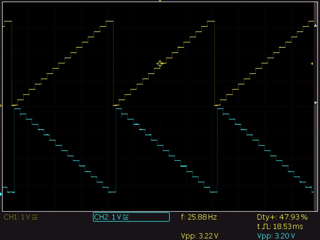
Besides a clock and an A/D converter, obviously there also was a D/A converter. The MNCAA can’t even generate interrupts and was maybe the simplest of all apart from MNCAG and MNCAM – but those are really extensions to MNCAD rather than modules in their own right. MNCAA is nice though, if you see what a simple BASIC program can do:
10 FOR I=-2047 to 2047 STEP 250
20 AOUT(,I,,,0)
30 AOUT(,-I,,,1)
40 NEXT I
50 GO TO 10
And then there are MNCDI and MNCDO. I started working on those two last, thinking they would be simple clones of the DR11C that I had already done. Well, almost. MNCDI has a couple interesting tricks – such as setting a mask for interrupts on specific wires in the 16-bit bus it works on, and even transitions on the upper 4 bits. Although the MINC BASIC doesn’t seem to support any of that…
And MNCDO had a special surprise – what for now passes as an error in one of the original XXDP test programs. I’m not quite convinced yet, because you don’t find those very often – it’s happened to me only once before, and I’ve found several four leaf clovers. It needs more investigation, let’s keep it at that for now.
The MINC BASIC is something to mention though. It makes it incredibly easy to interact with the modules, make them do something that will let the software interact with the outside world. Probably the same as you could do now with Arduino, Raspi, or something like Labview – but somehow a MINC feels so much more ‘real’… and it has way more blinkenlights too obviously. Must have been really something back in the day, to work with a MINC.
For now, PDP2011 has modules for MNCAD, MNCKW, MNCAA, MNCDI, and MNCDO. The other modules – MNCAG and MNCAM, being analog modules by definition, may not make much sense in the digital FPGA domain. How they are programmed from the MINC is a subject of further research though, I’ve not found any useful documentation about that.
Anyway, to close off this post, a bit of XXDP output. As the saying goes, a bit of output is worth a thousand words.
BOOTING UP XXDP-XM EXTENDED MONITOR


XXDP-XM EXTENDED MONITOR - XXDP V2.5
REVISION: F0
BOOTED FROM DL0
124KW OF MEMORY
UNIBUS SYSTEM

RESTART ADDRESS: 152000
TYPE "H" FOR HELP !

.R VMNF??
VMNFC0.BIC

MD-11-CVMNF-C   MINC-11 OPTION SIZER PROGRAM

DO YOU WANT THE MNCAD (A/D) CHANNEL MODE REPORT ?
                TYPE "Y" FOR YES =
DO YOU WANT THE MEMORY USAGE MAP REPORT ?
                TYPE "Y" FOR YES =
  ;MNCAD AT ADDRESS = 171000   VECTOR = 400
                 0 -  7 SINGLE ENDED
                10 - 17 SINGLE ENDED

  ;MNCKW AT ADDRESS = 171020   VECTOR = 440
  ;MNCKW AT ADDRESS = 171024   VECTOR = 450
  ;MNCAA AT ADDRESS = 171060   VECTOR =  **  DOES NOT EXIST **
  ;MNCDI AT ADDRESS = 171160   VECTOR = 130
  ;MNCDO AT ADDRESS = 171260   VECTOR = 340
# OF   ;MNCAD 1  ;MNCKW  2  ;MNCAA  1  ;MNCDI  1  ;MNCDO  1
MINC-11 MEMORY USAGE MAP        (EACH BIT = 2 ADDRESSES)
 ADDR       000/400          100/500          200/600          300/700
170000 0000000000000000 0000000000000000 1111111111111111 1111111111111111
170400 0000000000000000 0000000000000000 0000000000000000 0000000000000000
171000 1000110000001100 0000000000001100 0000000000001000 0000000000000000
171400 0000000000000000 0000000000000000 0000000000000000 0000000000000000
172000 0000000000000000 0000000000000000 0000000000000000 1111000011110000
172400 0000000000000000 0001000000000000 0000000000000000 0000000000000000
173000 1111111111111111 1111111111111111 1111111111111111 1111111111111111
173400 1111111111111111 1111111111111111 1111111111111111 1111111111111111
174000 0000000000000000 0000000000000000 0000000000000000 0000000000000000
174400 1100000000000000 0000000000000000 0000000000000000 0000000000000000
175000 0000000000000000 0000000000000000 0000000000000000 0000000000000000
175400 0000000000000000 0000000000000000 0000000000000000 0000000000000000
176000 0000000000000000 0000000000000000 0000000000000000 0000000000000000
176400 0000000000000000 0000000000000000 0000000000000000 0000000000000000
177000 0000000000000000 0000000000000000 0000000000000000 0000000000000000
177400 0000000000000000 0000000001001111 1111000011110000 0000000100000101

END PASS #     1
# OF   ;MNCAD 1  ;MNCKW  2  ;MNCAA  1  ;MNCDI  1  ;MNCDO  1